In chip thermal management, TIM1, TIM1.5, TIM2are frequently used technical terms, many practitioners easily confuse them, wrong material selection can directly cause cooling failure, and device damage. The threecore difference is mounting location, which in turn drives performance requirements, huge differences in material selection direction. Below we plainly explain the three thermal interface materials so you can quickly grasp selection essentials. TIMFull nameThermal Interface Material, i.e. thermal interface material, also called"thermal intermediary". Chips continuously generate heat during operation; heat-chip and the heatsink, cold plate and other cooling parts, look flat to the naked eye flat, are microscopically full of gaps, Air in those gaps conducts heat very poorly, severely impede heat transfer. TIM's core role: fill microscopic interfacial gaps, displace air, to reduce interfacial thermal resistance, so heat efficiently transfers from the chip to the cooling structure, prevent chip overheating and thermal throttling, /burnout and related issues. TIM1, TIM1.5, TIM2all belong toTIMcategory, classified by mounting location, each with its own role.
2. Core distinctions: TIM1/TIM1.5/TIM2 explained
TIM1|the first thermal barrier at the die core
Full name: primary thermal interface materialMounting location: bare die(Die)↔integrated heat spreader (IHS/Lid)(IHS/Lid), - the first structure conducting heat outward from the die core. Typical applications: high-compute packaged chips, e.g. AI GPU, high-end CPU, FPGA(Ascend, high-performance compute cards, etc.). Performance & material requirements
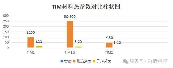
Heat flux here isDensityExtremely high(typically≥100W/cm², high-end chips can reach1000W/cm²), requirements are the most stringent:
Thermal Conductivity: ≥15W/m-K, high-end scenarios often useIndium Sheet, solder(Thermal Conductivityup to 86W/m-K);
Core criteria: ultra-low thermal resistance, high-temperature resistance, long-term operatingStable stability, materials must be compatible with the chip, and lid.
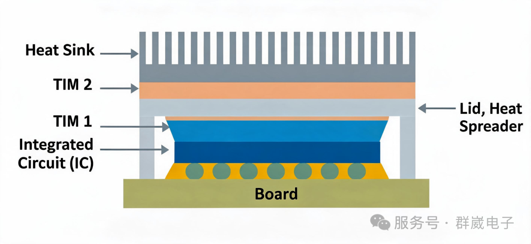
Figure reference: Cross-section of a lidded chip [1]
- TIM1.5|direct thermal bridge for lidless chipsTIM1.5is a special category, applied only to lidless(Lidless) packaged chips. Mounting location: bare die(Die)↔external heatsink/vapor chamber/cold plate, skipping the chip lid stage, the die core interfaces directly with external coolingSystem.
Typical applications
Mobile SoC, lidless packaginghigh-end notebookGPU, humanoid-robot main controllers, AIaccelerators, etc. Performance&material requirements
heat fluxDensitysecond only toTIM1, range is50-500W/cm²: Thermal Conductivity: 5-20W/m-K, mainstream choices includegallium-based Liquid Metal, high-conductivity phase-change materials, Graphenecomposites;
Core criteria: low interfacial thermal resistance, conform to irregular bare-die surfaces, while also supporting rework, removable needs.
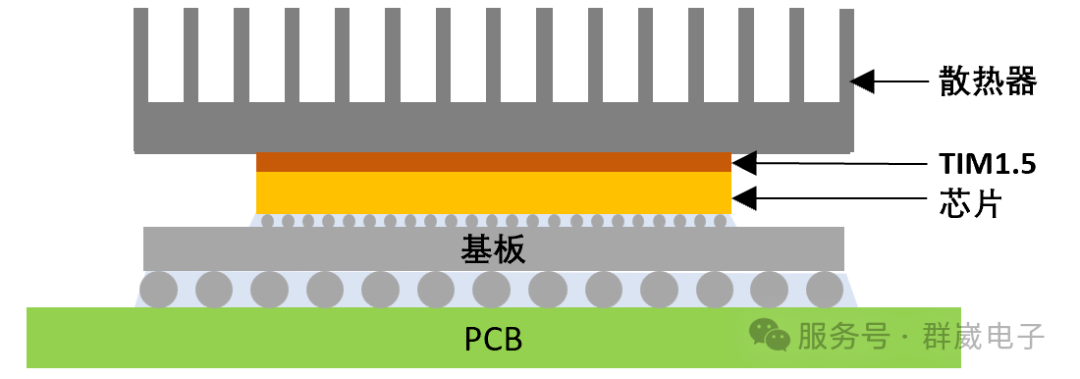
Figure reference: Schematic of lidless-chip cooling structure [2]
TIM2|System-level heat-transfer link
Full name: secondary thermal interface material
Mounting location: integrated heat spreader (IHS/Lid)(IHS)↔external heatsink, - the last link conducting chip heat to end-system coolingSystem "final link". Typical applications
All lidded chip devices, such as desktop/ServersCPU, industrial controllers, automotive electronics, mainstream notebook hardware, etc. Performance & material requirementsAfter heat spreads through the lid, heat fluxDensitydrops sharply(typically<50W/cm²), requirements are relatively relaxed, with more emphasis on practicality: Thermal Conductivity: mainstream2-6W/m-K, high-end products can reach8-12W/m-K, commonly use thermalthermal grease, thermal pads, phase-change materials, thermal gels;
Core criteria: electrical insulation(short-circuit prevention), good compressibility, anti-pump-out(no pump-out in long-term use), easy installation, reusable.
3. Core parameter comparison table(save for reference)
Type | Mounting location | heat fluxDensity | Thermal Conductivity | Core focus | Typical applications |
TIM1 | bare die→integrated heat spreader(IHS) | Extremely high(≥100 W/cm²) | ≥15 W/m-K(high-end 86 W/m-K) | ultra-low thermal resistance, high reliability | AI GPU, high-end CPU, FPGA |
TIM1.5 | bare die→external heatsink(lidless) | high (50-500 W/cm²) | 5-20 W/m-K | low resistance, bare-die fit, reworkable | Mobile SoC, lidless GPU, robot main controller |
TIM2 | integrated heat spreader(IHS)→external heatsink | mid/low(<50 W/cm²) | 1-12 W/m-K(mainstream 2-6 W/m-K) | easy installation, insulation, reusable | PC/Servers, industrial, automotive electronics |
Note: heat fluxDensityunitsW/cm², Thermal ConductivityunitsW/m-K.
4. Selection pitfalls to avoid: 3 core principles
Master the following rules, avoid selection mistakes at the root:
- Check chip package: With an integrated heat spreader, pair withTIM1+TIM2; lidless packaging, directly chooseTIM1.5.
- Check heat fluxDensity: Chip power, heat fluxDensity is higher, preferThermal Conductivity materials; for high power prefer solder, Liquid Metal, for mid/low power choose thermalthermal grease, thermal pads.
- Check use case: ConsumerDIYbuilds prefer cost-effective thermalthermal grease; industrial/server equipment preferhigh Stablephase-change materials, thermal gels; equipment needing frequent service/rework, choose removable, reusable thermal pads, gels.
5. Summary
Selection logic for the three materials always comes down to one rule: mounting location determines performance needs✅TIM1: die core→lid, focus onultimate thermal conduction, suited to ultra-high heat-flux scenarios; ✅TIM1.5: bare die directly to heatsink, focus onlow-resistance fit, easy rework, exclusive to lidless chips; ✅TIM2: lid→external heatsink, focus onpractical and convenient, insulationStable, suitable for most lidded devices. Together they form the complete chip cooling chain, select the right TIM as needed, to keep chipsStable running stably, and avoid thermal failures.
6. Industry practical experience
 TIM1.5level requires interface materials with high thermal conductivity and extremely low bond-line thickness. by Chongqing Qunwin Electronic Materials Co. Ltd.-developed and manufactured gallium-based Liquid Metal, processed from non-toxic metals gallium, indium, tin, zinc, , silver, etc. The product is liquid at room temperature, with ultra-highThermal Conductivity, about 5-10x that of high-endthermal grease 5-10x. perfectly fits this level. Also, , Leveraging Liquid Metalunique low interfacial thermal resistance and high flowability, It conforms tightly to microscopic roughness and unevenness on the bare die surface, minimizing contact thermal resistance caused by incomplete filling. In IHS(integrated heat spreader) high-performance scenarios(e.g. AIchip, high-end GPUs), Liquid Metaldirectly connects the chip to the cold plate, can drive thermal resistance to the limit at micron-scale thickness, handling kilowatt-class heatDensity challenges. In addition, , It can also widely serve high-power power electronics//energy-storage power-module cooling. Currently, , This product series has fully passed EURoHSenvironmental standard certification, combining high performance with green safety.
Save this article, use it as a checklist next time you select, and never again get confused by TIM1, TIM1.5, TIM2! If you have specific selection needs, leave a comment and let's discuss, discuss together~1.Thermal interface materialTIM1: The first critical heat path from die to heat spreader-Powder Circle2026-01-272.A new thermal-design option for high-power devices in datacom-China Thermal Design Network2023-05-08